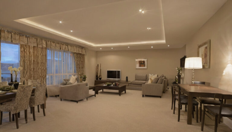
A Full-Size Mirror Mock-Up Removed Facial Shadows Before a Dubai Ensuite Ceiling Closed
Closing an ensuite ceiling before anyone checks a real face at the mirror can turn a small lighting adjustment into reopened plasterboard, moved conduits and disturbed tile setting-out. Hold the finishes until the interior decoration company can show how the proposed lighting performs at full scale.
Clients comparing responsibilities should first check whether the residential lighting scope includes testing and coordination. A reflected ceiling plan can locate fittings, but it cannot show eye-socket shadows, uneven side lighting or glare seen from the basin.
Key takeaways
- Reproduce the finished mirror, basin and viewing geometry before approving fixture positions.
- Measure vertical illuminance at fixed face positions and compare accepted and rejected arrangements under identical conditions.
- Coordinate side lights with tile joints, waterproofing, concealed services and fixing depths.
- Release finishes only when drawings, readings, photographs and exact product data form one traceable approval pack.
Six pre-closure approval gates
- Build the full-size viewing geometry.
- Measure light on the vertical face plane.
- Resolve fixture height and lateral position.
- Match the mock-up to product data.
- Record accepted and rejected arrangements.
- Verify the approval pack before releasing finishes.
A full-size mirror mock-up should precede ceiling closure in a Dubai ensuite
A full-size mirror mock-up lets the interior decoration company, lighting designer and electrical contractor assess a real face at the intended basin before cable points, ceiling cut-outs and finished walls become difficult to alter.
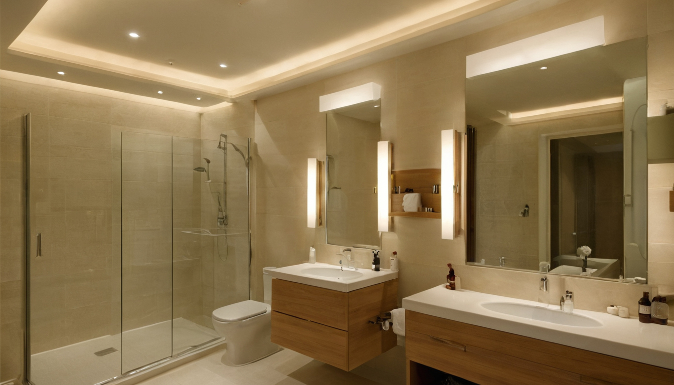
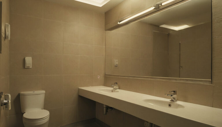
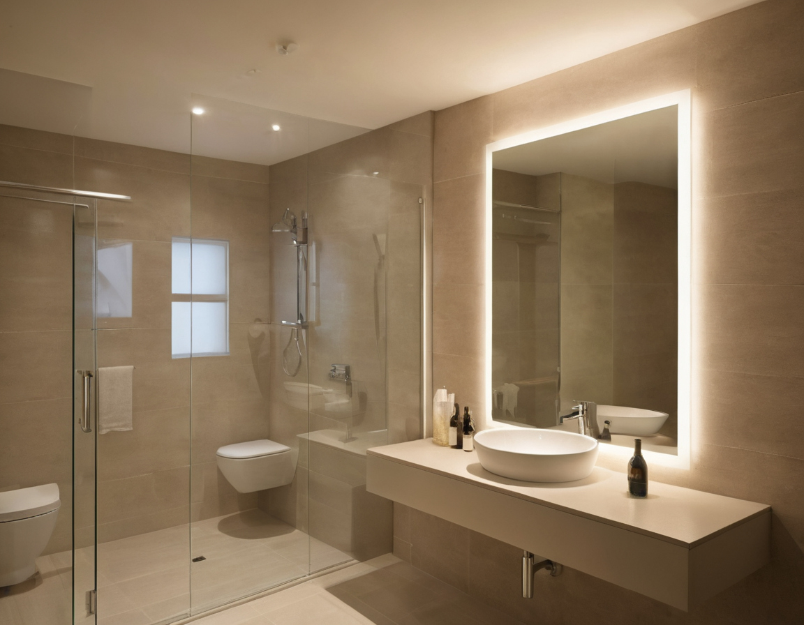
A full-size mirror mock-up should precede ceiling closure in a Dubai ensuite shown as an editorial planning reference.
The mirror mock-up must reproduce the finished viewing geometry
- Record whether the ensuite is in an apartment or villa, the anonymised test date, room dimensions, finished ceiling level and vanity-wall width.
- Reproduce the proposed mirror width, height and bottom-edge level in relation to the finished floor, basin centreline and counter.
- Mark normal standing positions and viewing distance rather than judging the light from the doorway.
- Represent cabinetry, pelmets, recesses and wall projections that could interrupt light reaching the face.
The record should identify the mirror or backing material, the problem that prompted the test and the roles authorised to accept or reject the arrangement. Record both outcomes. Documenting only the preferred result risks the one-sided testing associated with confirmation bias.
Ceiling closure is the practical lighting-design hold point
- Confirm the status of electrical first-fix, waterproofing, tiling, joinery and ceiling framing.
- Mark conduits, drivers, junction boxes, access panels and proposed fixture cut-outs.
- Identify whether moving a side light would penetrate the membrane or disrupt tile or stone setting-out.
- Confirm that each tested change remains reversible before closure.
Natural stone also needs protection during the trial. The Natural Stone Institute warns that abrasive scouring powders and creams can scratch stone surfaces. Once the mock-up geometry is credible and the finishes are protected, vertical measurements can reveal shadows that the ceiling plan cannot show.
Vertical illuminance at face positions reveals shadows that a ceiling plan cannot show
Assess mirror lighting on the vertical plane where faces are viewed, not only through horizontal readings at the counter or floor. The project record needs measurements at defined face positions, using the same fixtures, dimming state, ambient conditions and observer distances for every arrangement.
The accepted arrangement must be compared with the rejected arrangement at identical points
Before testing begins, a point-by-point schedule should establish the sensor height, vertical orientation and distance from the mirror. It should cover left, centre and right standing positions for representative observer heights. Moving the meter closer to a side light or changing its angle between tests weakens the comparison.
The site record should identify the light-meter manufacturer, model, asset or serial reference, calibration status and operating method. Record raw readings when taken, and photograph the meter at each marked location so another reviewer can check the coordinates.
Fixture output, dimmer level, supply conditions and other room lights must remain consistent. The record should also note daylight, blinds, open doors and temporary work lights. The interior decoration company should identify the current CIBSE or Society of Light and Lighting publication, edition and relevant guidance used by the project team rather than cite an unspecified benchmark.
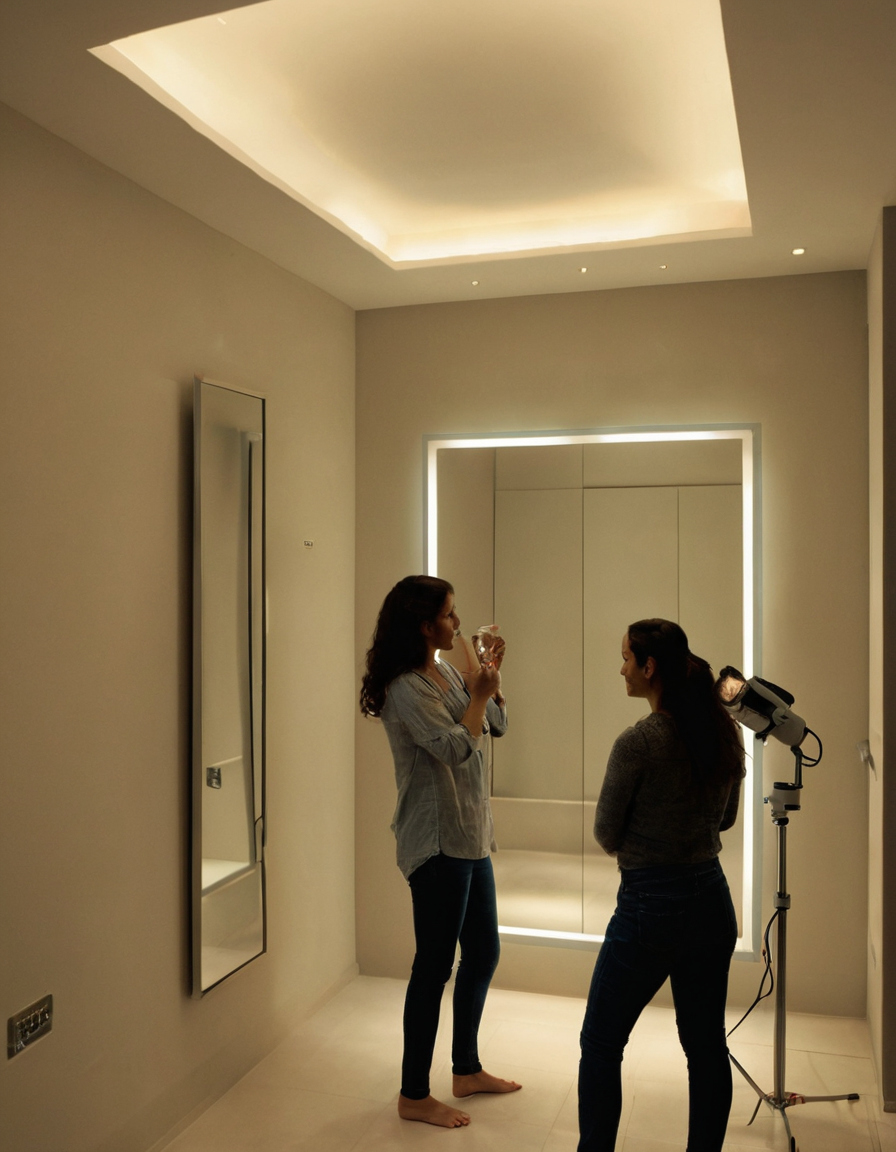
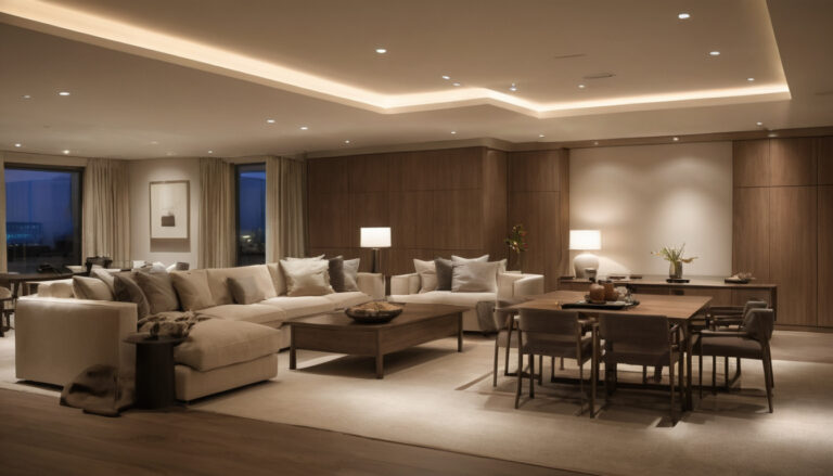
Vertical illuminance at face positions reveals shadows that a ceiling plan cannot show shown with practical context cues.
Measured illuminance does not replace a visual check for facial modelling
Illuminance readings show how much light reaches the measurement plane, but they do not fully describe shadows around the eyes, nose, chin and sides of the face. Fixed-position photographs and contemporaneous site notes should accompany every set of readings.
The visual record should state the observer positions and the acceptance criteria agreed before testing. Notes should describe visible effects, such as a hard shadow under the brow or stronger illumination on one cheek, rather than add impressions after approval.
Bathroom moisture remains a separate coordination issue. The U.S. Environmental Protection Agency advises fixing condensation and wet or damp spots promptly to help prevent mould growth. Lighting approval does not replace ventilation, moisture control or correction of leaks. With those responsibilities separated, the next decision concerns fixture geometry.
Fixture height and lateral placement determine whether mirror light reaches both sides of the face
Judge mirror-light positions against the actual mirror width, observer locations and fixture distribution, not a generic mounting rule. Approval requires a dimensioned elevation that records each tested luminaire centreline and the effect of every adjustment.
Side lighting and overhead lighting must be assessed as separate contributors
The mock-up record should identify which fixture group lights the front and sides of the face and which creates top-down shadows. Test side lights, ceiling lights and the combined scene under the same ambient conditions.
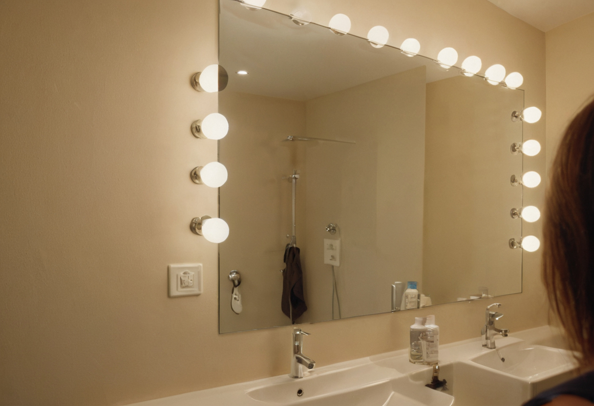
Fixture height and lateral placement determine whether mirror light reaches both sides of the face shown with practical context cues.
- Mark the mirror edges, basin centreline, observer positions and luminaire centrelines on one elevation.
- Record mounting height, lateral offset, orientation, tilt and distance from the finished wall.
- Measure and photograph each circuit separately before testing the combined scene.
- Record each movement and its observed effect at every defined face position.
- Confirm that the circuit schedule permits independent control where the design requires it.
A ceiling downlight may brighten the basin while leaving the eye sockets and underside of the chin in shadow. Review its offset, beam direction and relationship to the standing position separately before approving the cut-out. The ceiling team must then coordinate beam angles, circuits and ceiling access before fit-out.
Tile joints and waterproofed wall zones constrain the final side-light position
The visually preferred position is not buildable until it has been coordinated with the wall assembly. Before releasing finishes, check:
- the approved tile or stone module, joint width and setting-out drawing;
- the mirror support, adhesive zone and required edge clearance;
- the membrane extent and the manufacturer’s fixing and penetration instructions;
- the wall construction, fixing depth and concealed pipe, cable and conduit routes;
- the tolerance needed to keep both fittings aligned after tiling.
Where natural stone surrounds the mirror, the Natural Stone Institute recommends neutral cleaners, stone soap or mild liquid dishwashing detergent with warm water. Cleaning requirements do not determine fixture placement, but they should inform access and protection planning around the completed wall.
The lighting, electrical, tiling and waterproofing trades should accept the final elevation. The next test is whether the specified fitting can reproduce the mock-up result.
Photometric and colour data must support the mirror-light mock-up
A successful visual trial still needs traceable fixture data so the installed luminaires match the tested units. For each fitting and driver, the interior designing company should retain photometric files, output data, colour information, glare characteristics, control compatibility and evidence of suitability for the proposed bathroom position.
The installed fixture must match the photometric file used for approval
The sample label, datasheet, photometric filename, purchase order and delivered fitting should carry the same manufacturer and model code. Compare the optic, wattage, lumen package, finish and product revision. Data from a related fitting or different beam cannot validate the mock-up.
- Keep the manufacturer-issued IES or LDT file and record its issue date or revision.
- Retain the current datasheet covering output, distribution, electrical characteristics and installation limits.
- Record the driver model, dimming protocol and documented compatibility with the selected control.
- Check the ingress-protection rating against the actual fitting position, applicable Dubai or UAE requirements and the project specification.
A substitution after the mock-up requires a written technical comparison. Similar wattage does not establish similar distribution, glare or dimming behaviour. The team should also run a pre-finish dimmer and LED compatibility test before closing access to drivers and junction boxes.
Colour quality should be reported without unsupported appearance claims
The approval record should state the manufacturer-reported correlated colour temperature, specified tolerance, CRI and any published individual colour-sample or TM-30 data. It should also identify the colour temperature of other luminaires operating during the accepted scene.
A single colour metric does not prove that every face will appear flattering. The mock-up supplies the visual evidence; the manufacturer data identifies the equipment that produced it. Keeping accepted and rejected records also reduces the risk that reviewers favour expected results while ignoring contrary observations, a behaviour described in the approved reference on confirmation bias.
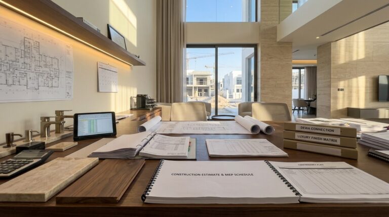
Photometric and colour data must support the mirror-light mock-up shown as an editorial planning reference.
Finish work can introduce a separate indoor-air issue. The U.S. Environmental Protection Agency identifies paints, varnishes, waxes, cleaning products, building materials and furnishings as common indoor sources of volatile organic compounds and recommends increased ventilation when products emitting these compounds are used. This requirement belongs in the finishing plan, not in the photometric assessment.
The accepted and rejected mirror-light arrangements require a traceable comparison
Place rejected and accepted arrangements together in one compact comparison. Each entry must identify geometry, control state, vertical readings, facial-shadow pattern, glare response, coordination consequence and decision under the same ensuite conditions.
A comparison table should separate measurements from site observations
Rejected arrangement
- Coordinates: fixture positions from finished floor level, mirror edges and basin centreline.
- Control state: active circuits, dimmer levels and ambient lighting conditions.
- Readings: vertical illuminance at every marked face position.
- Observed effect: shadows, uneven side lighting or direct glare, with the observer identified.
- Decision: reason for rejection and required adjustment.
Accepted arrangement
- Coordinates: revised positions measured from the same references.
- Control state: the same operating conditions used for the rejected test.
- Readings: repeated measurements at identical points.
- Observed effect: recorded change in facial illumination, shadows and glare.
- Decision: accepted revision, remaining limitations and coordination consequences.
Instrument readings and visual observations answer different questions. The meter documents illuminance at a defined point; the observer records facial modelling and glare. Mark missing information “not recorded” rather than reconstructing it later.
Site photographs should show why the final arrangement was approved
Photographs should include a wide view showing the mirror, luminaires and observer positions, plus accepted and rejected views from matching camera positions. Decorative photographs of the completed room cannot replace contemporaneous evidence.
Energy performance cannot stand in for facial-lighting evidence either. ENERGY STAR states that qualified LED lighting uses at least 75 percent less energy and lasts up to 25 times longer than incandescent lighting, but those figures do not establish distribution, glare or suitability at a mirror.
Clients can verify mirror-light testing before approving bathroom finishes
Before approving ceiling closure or vanity-wall finishes, the client should ask for a dimensioned mock-up record, repeatable readings, fixture-specific evidence and written coordination approval. Each bathroom still requires adjustment for its geometry, users, fittings and applicable requirements.
A mirror-light approval pack should contain five verifiable items
- Mock-up geometry: a dated plan and vanity elevation showing the mirror, basin centreline, observer positions, finished ceiling level and tested luminaire locations.
- Measurement record: vertical readings with meter details, sensor position, ambient conditions and control state, plus matching photographs.
- Product evidence: exact luminaire and driver codes, current datasheets, colour information and matching IES or LDT files.
- Coordinated drawings: ceiling cut-outs, conduits, drivers, junction boxes, access panels, tile joints, wall build-up and waterproofing penetrations.
- Written acceptance: document names, revisions, approval dates and recorded acceptance from the authorised parties.
Unrecorded assumptions should delay irreversible finish approval
A missing ceiling coordination drawing, fixture code that differs from the tested sample, unexplained reading or moved wall outlet requires another review. Keep the hold point in place until each deviation between the mock-up, approved drawing and installed work has been logged, assessed and accepted.
Release the ceiling and wall finishes only when the installed arrangement matches a traceable approval pack. For a Dubai ensuite consultation, bring the vanity elevation, ceiling coordination drawing, luminaire schedule and proposed finish build-up so the mirror-light test can be planned before closure.